1 Scope
1.1 This European Standard applies to oil hardened and tempered spring steel wire made from unalloyed or alloyed steels. They are primarily subject to torsional stresses such as in coil springs for compression and extension and in special cases also for applications where the spring wire is subject to bending stresses such as lever springs.
As a rule unalloyed steels are used for applications at room temperature whereas alloyed steels are generally used at a temperature above room temperature. Alloyed steels may also be chosen for above average tensile strengths.
1.2 In addition to this European Standard, the general technical delivery requirements of EN 10021 are applicable.
2 Normative references
The following referenced documents are indispensable for the application of this document. For dated references, only the edition cited applies. For undated references, the latest edition of the referenced document (including any amendments) applies.
EN 10021, General technical delivery conditions for steel products
EN 10204:2004, Metallic products – Types of inspection documents
EN 10218-1:2011, Steel wire and wire products一Genera/- Part 1: Test methods
EN 10218-2, Steel wire and wire products一General 一Part 2: Wire dimensions and tolerances
EN 10247, Micrographic examination of the non-metallic inclusion content of steels using standard pictures
CEN/TR 10261, lron and steel一Review of available methods of chemical analysis
EN ISO 377, Steel and stee/ products – – Location and preparation of samples and test pieces for mechanical testing (ISO 377:1997)
EN ISO 3887, Steels – – Determination of depth of decarburization (ISO 3887:2003)
EN ISO 6892-1, Metallic materials – Tensile testing – Part 1: Method of test at room temperature (ISO 6892-1:2009)
EN ISO 14284, Steel and iron – Sampling and preparation of samples for the determination of chemical composition (ISO 14284:1996)
ISO 7800, Metallic materials – Wire – Simple torsion test
3 Terms and definitions
For the purposes of this document, the following terms and definitions apply.
3.1 oil hardened and tempered spring steel wire
wire that is heat treated in line in the following way: it is first transformed into austenite, quenched in oil or similar quenching medium, followed immediately by tempering by heating to the appropriate temperature
4 Classification
This standard deals with all types of hardened and tempered spring steel wire. The grade for normal applications made from unalloyed or alloyed steel has the abbreviation FD and is intended for static applications.
Spring steel wire for medium fatigue levels, such as required for some clutch springs from unalloyed or alloyed steel, has the abbreviation TD.
Spring steel wire from unalloyed steel or alloyed steel intended for use under severe dynamic duty such as for valve springs or other springs with similar requirements has the abbreviation VD.
The diameter ranges for the various wire grades are shown in Table 1.
Table 1一Spring wire grades and diameter range

Medium and high fatigue grades TD and VD are characterized by high steel cleanliness, specific chemical, mechanical and technological parameters and a well defined surface condition in relation to the allowable depth of surface defects and decarburization.
The static grade FD is characterized by its chemical, mechanical and technological characteristics as well as by a specified surface condition concerning surface defects and decarburization.
5 Information to be supplied by the purchaser
The purchaser shall clearly state in his enquiry or order the product and following information:
a) the desired quantity;
b) the term spring steel wire or straightened and cut lengths;
c) the number of this European standard: EN 10270-2;
d) the steel grade (see Tables 1 and 2);
e) the nominal wire diameter selected from Tables 4 or 5 and for cut length the length and the length tolerance class (see Table 9);
f) the form of delivery and unit mass (see 6.1);
g) the type of inspection document;
h) any particular agreement.
EXAMPLE
5 t oil hardened and tempered spring steel wire according to this standard, grade VDC, nominal diameter
2,50 mm in coils of about 300 kg; inspection document 3.1 according to EN 10204:2004:
5 t spring steel wire EN 10270-2 – VDC-2,50 in coils of about 300 kg; EN 10204:2004 – 3.1
6 Requirements
6.1 Form of delivery
6.1.1 Oil hardened and tempered wire shall be supplied in coils, on spools or in cut lengths. The wire in coils or on spools shall form one continuous length. Wire in coil may also be supplied on carriers containing one or more coils.
For “VD” and “TD” grades no welds are permitted after the heat treatments preceding the final drawing operation; for “FD” grades no welds shall be made at finished size unless agreed otherwise between the parties.
6.1.2 The supplied wire units shall be tightly bound to ensure that wire spiral waps do not spring out unexpectedly. The starting end shall be marked and at the coil ends the wire shall be covered with a protective cap.
6.2 Surface finish
The wire shall be protected against corrosion and mechanical damage. Unless otherwise specified the wire shall be delivered in slightly oiled condition.
6.3 Chemical composition
The steel is characterized by the heat analysis which shall be in accordance with the values of Table 2. The permissible deviation of the product analysis from the limiting values of heat analysis shall be in accordance with Table 3.
6.4 Non metallic inclusions
The “VD” grades shall be checked for maximum size of inclusion according to EN 10247. The allowable level of inclusions shall be agreed between the parties at the enquiry and order.
6.5 Mechanical properties
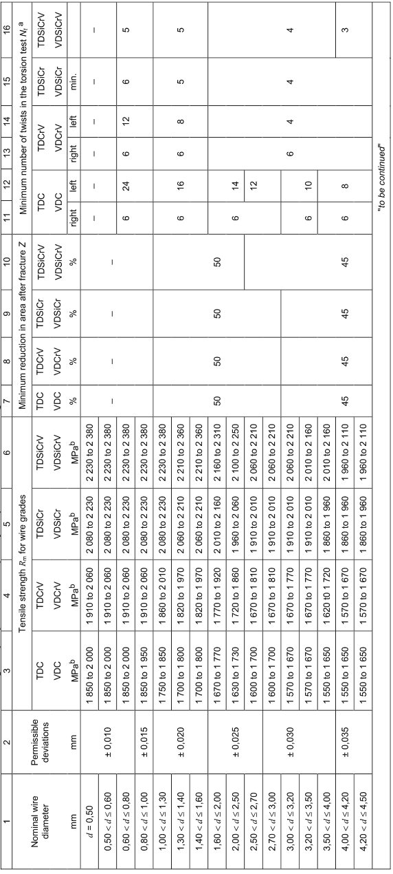
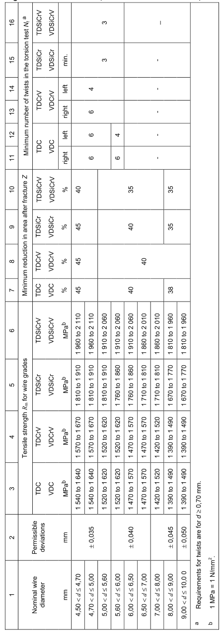
For tensile strength Rm and reduction in area after fracture (Z) the wire grades shall satisfy the values listed in Tables 4 and 5. Reduction of area is measured only for size 1,00 mm and above (see Tables 4, 5 and 11).
The range of the tensile strength values within a coil/reel shall not exceed 50 MPa for the grades “VD”, 60 MPa for the grades “TD” and 70 MPa for the grades “FD”.
Table 2一Chemical composition, % by mass
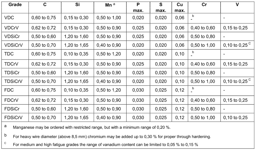
Table 3- Permissible deviation of the product analysis from the limiting values for the heat analysis
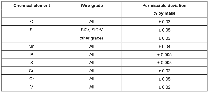
Table 4 – Mechanical and technological properties and quality requirements for wire grades FDC, FDCrV, FDSiCr and FDSiCrV
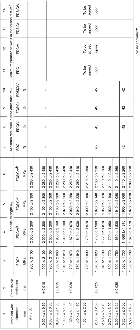
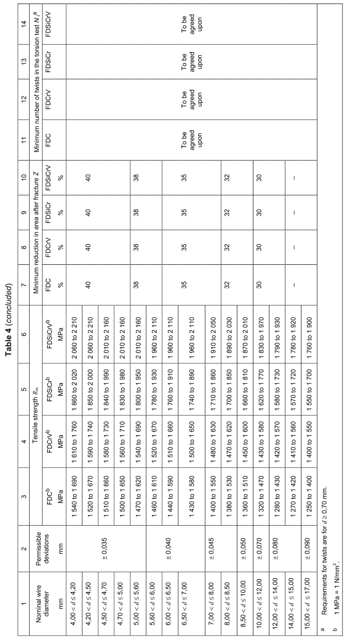
Table 5 – Mechanical and technological properties and quality requirements for wire grades TDC, TDCrV, TDSiCr, TDSiCrV, VDC, VDCrV, VDSiCr and VDSiCrV
6.6 Technological properties
6.6.1 Coiling test
In order to assess the uniformity of the wire in the colling deformation and its surface condition the coiling test may be carried out on samples up to 0,70 mm diameter.
In the test as described further in 7.4.3 the test piece shall exhibit a defect-free surface without splits or fracture and a uniform pitch of the turns after coiling.
NOTE
Although the usefulness of the coiling test is not generally recognized, it has been retained since it offers the possibility of revealing internal stresses. If doubtful test results are obtained the wire concerned should not be rejected immediately but efforts should be made by the parties concerned to elucidate the cause.
6.6.2 Simple torsion test
The torsion test is carried out for assessing deformability, fracture behaviour and surface condition for sizes from 0,70 mm to 6,00 mm. The wires grades “VD” and “TD” shall satisfy the minimum requirements of Table 5.
The fracture of the torsion test piece shall be smooth and perpendicular to the wire axis. The fracture shall be Type 1a as per EN 10218- 1:2011. The rupture shall show no longitudinal cracks.
For the grade “FD” wire the torsion test is applied for sizes from 0,70 mm to 6,00 mm. The test piece shall be twisted in one direction until fracture. The fracture shall show a flat surface Type 1a or 3a according to EN 10218-1:2011.
Minimum values for the numbers of torsions required for grade “FD” may be agreed at the time of order.
6.7 Surface quality
6.7.1 The surface of the wire shall be smooth and permissible depth of surface defects at the coil ends shall be in accordance with Table 6.
If needed for VD grade the wire can be shaved or ground.
By Eddy current testing of surface defects the areas of the coil with defects above the level of Table 7 shall be marked. This testing is not performed for FD-grades. The number of defective parts that can be tolerated may be agreed between the parties.
Table 6一Permissible depth of surface defects (mm)

Table 7一Permissible surface defects by Eddy current testing

6.7.2 Surface decarburization
The wire grades according to this standard shall be free from total decarburization. The maximum depths of the partially decarburized zone shall be checked at the end of the coils. The permissible depth is shown in Table 8.
If needed for VD and TD grades the wire can be shaved or ground.
Table 8一Permissible depth of surface decarburization (mm)

6.8 Dimensions and dimensional tolerances
6.8.1 Dimensional tolerances
a) Wire in coils
The tolerances level for the wire diameter is based on EN 10218-2 level:
1) T5 for wire diameter up to and including 0,80 mm;
2) T4 for wire diameter above 0,80 mm up to 10,00 mm;
3) T3 for wire diameter above 10,00 mm;
b) Wire in cut lengths
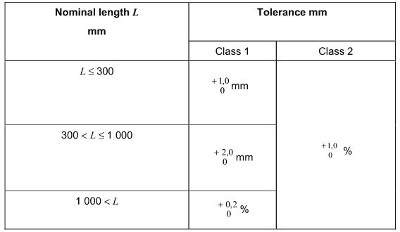
The requirements for length tolerances and straightness are as in EN 10218-2. The tolerance on the nominal length shall only be in plus keeping the same tolerance range (Table 9).
Table 9- Tolerances on the length of cut lengths
6.8.2 Out of roundness
The out of roundness, i.e. the difference between the maximum and minimum diameter of the wire at the same cross section, shall not be more than 50 % of the total permissible deviation specified in Tables 4 and 5.
7 Testing and inspection
7.1 Inspection and inspection documents
Products according to this standard shall be delivered with specific testing (see EN 10021) and the relevant inspection document (see EN 10204) agreed at the time of enquiry and order.
The inspection document shall include the following information:
-heat analysis;
-result of the tensile test (Rm and Z);
-result of the torsion test (N);
-actual wire diameter;
-results of optional tests agreed.
7.2 Extent of testing for specific inspection
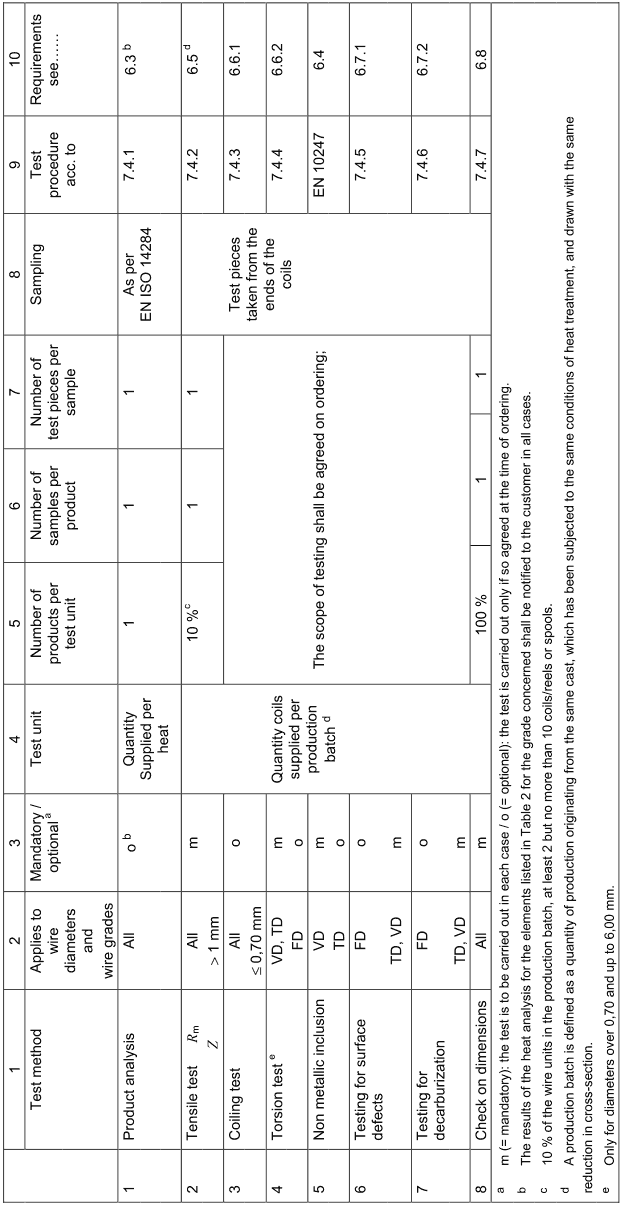
The extent of testing shall be in accordance with Table 11.
7.3 Sampling
Sampling and testing preparation shall be in accordance with EN ISO 377 and EN ISO 14284.
Samples shall be taken at the end of the units. Table 11/column 8 gives further details.
7.4 Test methods
7.4.1 Chemical composition
Unless otherwise agreed at the time of ordering the choice of a suitable physical or chemical method of analysis for the determination of product analysis shall be at the discretion of the supplier.
In cases of dispute the analysis shall be carried out by a laboratory approved by the two parties. The method of analysis to be applied shall be agreed upon, where possible in accordance with CEN/TR 10261.
7.4.2 Tensile test
The tensile test shall be carried out according to EN ISO 6892-1, on samples with the full cross-section of the wire. For the calculation of the tensile strength the actual cross-section based on the actual wire diameter is applied.
7.4.3 Coiling test
The coiling test shall be carried out in the following manner: A test piece – approximately 500 mm in length – shall be closely wound, under slight but reasonably uniform tension on a mandrel three to three and a half times the nominal diameter. The mandrel diameter shall however be at least 1,00 mm. The close coil shall be stretched so that after releasing the stress it sets to approximately three times its original length.
The surface condition of the wire and the regularity of the spring pitch and individual windings shall be inspected with the test piece in this condition.
7.4.4 Simple torsion test
The torsion test shall be carried out according to ISO 7800.
For the grade “FD” the test is continued in one direction until fracture. For wire grades TDC, TDCrV, VDC and VDCrV the test piece is first twisted in one direction – the number of twists indicated in Table 5- and is then twisted in the other direction until fracture.
7.4.5 Surface defects
Testing for surface defects shall be carried out on test pieces taken from both ends of the wire units either by deep etching or microscopically, using polished metallographic sections. It may be agreed for wire diameters below 2,00 mm at the time of enquiry and ordering that microscopic testing be carried out immediately after the last heat treatment.
The deep etch test shall be executed according to EN 10218-1 or alternatiely by the following method:
The section of the wire to be tested shall be first suitably degreased, followed by etching using a solution of 50 volume % hydrochloric acid and 50 volume % water, heated to (75 +8) °C, until the diameter has been reduced by about 1 % with a maximum of 0,03 mm. If surface defects are detected, their depth shall be determined using, for example polished section, or by the stylus method. Cases of dispute shall be settled on the basis of the radial depth measured at a magnification of X 200.
For the grades of the type “TD” and “VD” in the diameter range 2,50 mm to 8,00 mm the total length of the coil shall be tested in line by an appropriate non-destructive test. All the areas with defects above the allowable level as shown in Table 7 shall be clearly and permanently marked.
7.4.6 Decarburization
The depth of decarburization shall be inspected by metallographic means. The test pieces are taken at the ends of the wire unit. Evaluation shall be performed on the transverse section of test pieces etched with nital and at magnification of x 200 in accordance with EN ISO 3887.
7.4.7 Diameter
The diameter shall be measured using limit gauges, a micrometer or any suitable method. The out of roundness shall be determined as the difference between the maximum and minimum diameters at any one cross-section.
7.5 Retests
Retests shall be performed according to EN 10021.
8 Marking and packaging
Each unit shall be properly marked and identified so as to permit traceability and reference to the inspection documents.
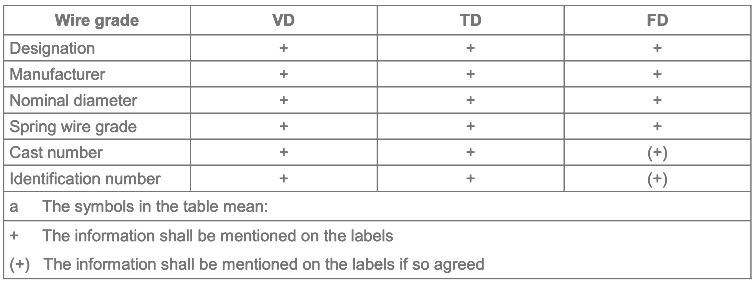
The labels shall withstand normal handling and contact with oil; they shall show at least the information according to Table 10. Other information shall be subject to an arrangement between the parties.
Wire shipments shall be suitably protected against mechanical damage and/or contamination during transport.
Table 10一Information on the labelsa
